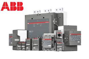
1SBH136001R2122
NFZ22E-21 24-60V50/60HZ 20-60VDC Relay
Trade Price
£80.98
Per
1
Unit
EA
Pack Quantity
1

Information
NFZ 4 pole contactor relays - AC/DC operated, low consumption * Part number: NFZ22E-21 * NF contactor relays are used for switching auxiliary and control circuits. * These contactor relays are of the block type design with: * 4 poles. Contactor relays have mechanically linked auxiliary contact elements (side-marked symbol) * Control circuit: AC or DC operated with electronic coil interface accepting a wide control voltage range (e.g. 100...250 V AC and DC) - can manage large control voltage variations - only 4 control voltage ranges covering 24...500 V 50/60 Hz and 20...500 V DC - reduced panel energy consumption - very distinct closing and opening. - allow direct control by PLC-output = 24 V DC 500 mA - can withstand short voltage dips and voltage sags * Built-in surge suppression * Add-on auxiliary contact blocks for front or side mounting and a wide range of accessories
Technical Specifications
Minimum Order Quantity
1 piece
Customs Tariff Number
85364900
Product Net Width
45 mm
Product Net Depth / Length
77 mm
Product Net Height
86 mm
Product Net Weight
0.31 kg
Number of Auxiliary Contacts NO
2
Number of Auxiliary Contacts NC
2
Standards
IEC/EN 60947-1, IEC/EN 60947-5-1, UL 508, CSA C22.2 No. 14-13
Rated Operational Voltage
Auxiliary Circuit 690 V
Rated Frequency (f)
Auxiliary Circuit 50 / 60 HzControl Circuit 50 / 60 Hz
Conventional Free-air Thermal Current (Ith)
acc. to IEC 60947-5-1, Θ = 40 °C 16 A
Rated Operational Current AC-15 (Ie)
(500 V) 2 A(690 V) 2 A(24 / 127 V) 6 A(220 / 240 V) 4 A(400 / 440 V) 3 A
Rated Short-time Withstand Current Low Voltage (Icw)
for 0.1 s 140 Afor 1 s 100 A
Maximum Electrical Switching Frequency
(AC-15) 1200 cycles per hour(DC-13) 900 cycles per hour
Rated Operational Current DC-13 (Ie)
(24 V) 6 A / 144 W(48 V) 2.8 A / 134 W(72 V) 1 A / 72 W(110 V) 0.55 A / 60 W(125 V) 0.55 A / 69 W(220 V) 0.27 A / 60 W(250 V) 0.27 A / 68 W(400 V) 0.15 A / 60 W(500 V) 0.13 A / 65 W(600 V) 0.1 A / 60 W
Rated Insulation Voltage (Ui)
acc. to IEC 60947-5-1 690 Vacc. to UL/CSA 600 V
Rated Impulse Withstand Voltage (Uimp)
6 kV
Maximum Mechanical Switching Frequency
6000 cycles per hour
Rated Control Circuit Voltage (Uc)
50 Hz 24 ... 60 V60 Hz 24 ... 60 VDC Operation 20 ... 60 V
Operate Time
Between Coil De-energization and NC Contact Closing 13 ... 98 msBetween Coil De-energization and NO Contact Opening 11 ... 95 msBetween Coil Energization and NC Contact Opening 38 ... 90 msBetween Coil Energization and NO Contact Closing 40 ... 95 ms
Mounting on DIN Rail
TH35-15 (35 x 15 mm Mounting Rail) acc. to IEC 60715TH35-7.5 (35 x 7.5 mm Mounting Rail) acc. to IEC 60715
Mounting by Screws (not supplied)
2 x M4 screws placed diagonally
Connecting Capacity Auxiliary Circuit
Flexible with Ferrule 1/2x 0.75 ... 2.5 mm²Flexible with Insulated Ferrule 1x 0.75 ... 2.5 mm²Flexible with Insulated Ferrule 2x 0.75 ... 1.5 mm²Rigid Solid 1/2x 1 ... 2.5 mm²Rigid Stranded 1/2x 1 ... 2.5 mm²
Connecting Capacity Control Circuit
Flexible with Ferrule 1/2x 0.75 ... 2.5 mm²Flexible with Insulated Ferrule 1x 0.75 ... 2.5 mm²Flexible with Insulated Ferrule 2x 0.75 ... 1.5 mm²Rigid Solid 1/2x 1 ... 2.5 mm²Rigid Stranded 1/2x 1 ... 2.5 mm²
Wire Stripping Length
Auxiliary Circuit 10 mmControl Circuit 10 mm
Degree of Protection
acc. to IEC 60529, IEC 60947-1, EN 60529 Auxiliary Terminals IP20acc. to IEC 60529, IEC 60947-1, EN 60529 Coil Terminals IP20
Terminal Type
Screw Terminals
Connecting Capacity Auxiliary Circuit UL/CSA
Rigid Solid 1/2x 18-14 AWGRigid Stranded 1/2x 18-14 AWG
Tightening Torque UL/CSA
Auxiliary Circuit 11 in·lbControl Circuit 11 in·lb
Ambient Air Temperature
Close to Contactor for Storage -60 ... +80 °CNear Contactor for Operation in Free Air -40 ... 70 °C
Climatic Withstand
Category B according to IEC 60947-1 Annex Q
Maximum Operating Altitude Permissible
Without Derating 3000 m
Resistance to Shock acc. to IEC 60068-2-27
Closed, Shock Direction: B1 25 gOpen, Shock Direction: B1 5 gShock Direction: A 30 gShock Direction: B2 15 gShock Direction: C1 25 gShock Direction: C2 25 g
Resistance to Vibrations acc. to IEC 60068-2-6
5 ... 300 Hz 4 g closed position / 2 g open position
RoHS Status
Following EU Directive 2011/65/EU
Package Level 1 Units
box 1 piece
Package Level 1 Width
87 mm
Package Level 1 Depth / Length
79 mm
Package Level 1 Height
47 mm
Package Level 1 Gross Weight
0.31 kg
Package Level 1 EAN
3471523101715
Package Level 2 Units
box 27 piece
Package Level 2 Width
250 mm
Package Level 2 Depth / Length
300 mm
Package Level 2 Height
315 mm
Package Level 2 Gross Weight
16.74 kg
Package Level 3 Units
1296 piece
Object Classification Code
K
ETIM 4
EC000196 - Contactor relay
ETIM 5
EC000196 - Contactor relay
ETIM 6
EC000196 - Contactor relay
ETIM 7
EC000196 - Contactor relay
ETIM 8
EC000196 - Contactor relay
eClass
V11.0 : 27371001
UNSPSC
39121529
IDEA Granular Category Code (IGCC)
4763 >> Power contactor, DC switching
E-Number (Finland)
3706404
E-Number (Sweden)
3211446
Document Links
Datasheet

