
NZM3-XBSM
Interface module PXR20
Trade Price
£161.03
Per
1
Unit
EACH
Pack Quantity


Information
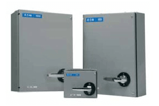
Eaton Moeller series NZM - Molded Case Circuit Breaker. Interface module for NZM3 PXR20, connection for communication
Technical Specifications
Product Length/Depth
0.001 mm
Product Height
0.001 mm
Product Width
0.001 mm
Product Weight
0.001 kg
Compliances
IEC
UL/CSA
RoHS conform
Terminal capacity (stranded cable)
0.2 mm² - 1.5 mm² (1x) at supply connection
0.25 mm² - 0.75 mm² (1x) at supply connection (insulated ferrule according to DIN46224 / 4)
0.25 mm² - 0.75 mm² (1x) at supply connection (uninsulated ferrule according to DIN46224 / 1)
24 - 16 AWG (1x) at supply connection
10.11 Short-circuit rating
Is the panel builder's responsibility. The specifications for the switchgear must be observed.
Frame
NZM3
Accessory/spare part type
Interface module
Communication and measuring function
Accessory
Terminal capacity (solid cable)
0.2 mm² - 1.5 mm² (1x) at supply connection
10.4 Clearances and creepage distances
Meets the product standard's requirements.
10.12 Electromagnetic compatibility
Is the panel builder's responsibility. The specifications for the switchgear must be observed.
Current consumption - max
100 mA
Strip length
5 mm (supply connection)
10.2.5 Lifting
Does not apply, since the entire switchgear needs to be evaluated.
10.2.3.1 Verification of thermal stability of enclosures
Meets the product standard's requirements.
10.2.3.2 Verification of resistance of insulating materials to normal heat
Meets the product standard's requirements.
10.2.3.3 Resist. of insul. mat. to abnormal heat/fire by internal elect. effects
Meets the product standard's requirements.
10.8 Connections for external conductors
Is the panel builder's responsibility.
Connection type
10-pin plug connector (internal COM connection)
5-pin plug connector (CAM connection)
Assembled CAM cable (Supply connection, Digital-input)
With push in terminal
Pre-wired cable to the Modbus module (internal COM connection)
Screw terminal (supply connection, rated control voltage)
With bolt connection
Voltage rating
24 V DC
10.9.2 Power-frequency electric strength
Is the panel builder's responsibility.
Degree of protection
Installation in the switch
Special features
For universal connection of optional circuit breaker functions.
Required for communication
The connection types depend on the design of the interface module.
Circuit breaker status detection (I, +, 0) for the electronic trip unit.
The switch's status can be communicated.
24 V DC auxiliary power connection.
Connection for Communications Adapter Module (CAM).
Optional CAM available for various Fieldbus communication systems (Profibus DP, SmartWire-DT, Ethernet-based Fieldbus).
Connection to optional, internal Modbus RTU module.
Mechanical pass-through of the switch's status (I, O) for use by the remote operator.
10.7 Internal electrical circuits and connections
Is the panel builder's responsibility.
10.10 Temperature rise
The panel builder is responsible for the temperature rise calculation. Eaton will provide heat dissipation data for the devices.
Tightening torque
>= 0.22 Nm
<= 0.25 Nm
Control voltage tolerance
+/- 20%
10.9.3 Impulse withstand voltage
Is the panel builder's responsibility.
Type
Accessory
Interface module
10.2.2 Corrosion resistance
Meets the product standard's requirements.
10.6 Incorporation of switching devices and components
Does not apply, since the entire switchgear needs to be evaluated.
10.2.4 Resistance to ultra-violet (UV) radiation
Meets the product standard's requirements.
10.2.7 Inscriptions
Meets the product standard's requirements.
10.5 Protection against electric shock
Does not apply, since the entire switchgear needs to be evaluated.
Used with
NZM3(-4)-VX(MX)(PX)(PMX)…
10.13 Mechanical function
The device meets the requirements, provided the information in the instruction leaflet (IL) is observed.
10.2.6 Mechanical impact
Does not apply, since the entire switchgear needs to be evaluated.
10.9.4 Testing of enclosures made of insulating material
Is the panel builder's responsibility.
10.3 Degree of protection of assemblies
Does not apply, since the entire switchgear needs to be evaluated.
Document Links
Datasheet